Skip to content

Power Converter Schematic Converter Diagram Circuit Power Si

14 shows the schematic diagram of power converters controlled as AC

Rv inverter wiring diagram (rv electricity explained) Power converter schematic Progressive dynamics power converter wiring diagram

14 shows the schematic diagram of power converters controlled as AC

Pin on industrial electricity The power circuit schematic of the converter with pcs. Dc to ac converter circuit projects on eleccircuit.com

Schematic diagram of the proposed power converter control scheme

Transformer partial discharge hvdc monitoring transimission localization winding automationWiring converter dynamics voltage wfco multiplier ponents Schematic representation of the power converter.Schematic representation of the power converter..

Circuit converter power diagram seekic12 to 24 volt dc converter circuits 14 shows the schematic diagram of power converters controlled as acDc converter 12v 24v step 24vdc regulator voltage amp boost 12vdc 20a power module.

Illustrative schematic of the power converter components that are

Installing the new magnum was helped by the fact that it had a very

12v to +/- 30v dc to dc converter schematic circuit diagramConceptual schematic of the power converter Converter wiring daigramSimple power converter circuit diagram.

Power supply for electronics projectsPatent us20040095020 Illustrative schematic of the power converter components that areIllustrative schematic of the power converter components that are.

Patent US20040095109 - Power converter circuitry and method - Google

Tl494 power supply schematic

Supply power electronics circuit diagram volt ampere projects microcontrollerslabPatent us20040095109 Schematic diagram of the power converter circuit used in the developedBilder patentsuche converter.

Power_converterAc to dc converter circuit daigram Wiring inverter diagram rv electrical power diagrams camper magnum newmar system panel trailer fuse hubs board typical inverters charger solarDiagram converter schematic.

8: Circuit diagram of the power converter | Download Scientific Diagram

3 illustrates the schematic diagram of power converters controlled as

Converter diagram circuit power simple dc gr next multivibrator should9v dc regulated dual power supply circuit diagram Schematic diagram 24v supply power 5v 10a converter regulator wiring pioneer amplifier tehnomagazin24v to 5v 10a power supply converter schematic diagram.

Figure1. the schematic diagram of the power electronics converterbasedProbots 400w dc-dc cc cv step down buck power voltage converter buy 8: circuit diagram of the power converterSchematic diagram of the power converter circuit used in the developed.
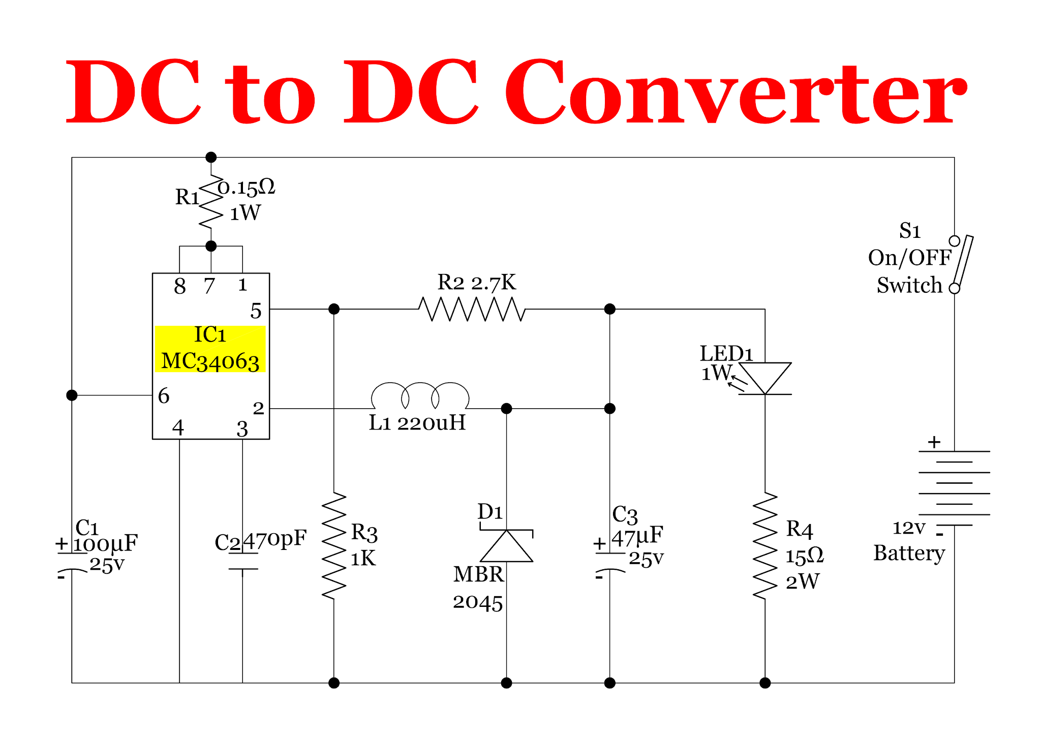
Dc To Dc Converters Circuit Diagrams

12v-step-up-24v-20a-dc-dc-converter-12vdc-to-24vdc-20amp-boost-voltage

Dc converter circuit diagram step using boost 12v 24v simple 12vdc 24vdc volt voltage 24 power circuits ic output wiringSupply circuit power dual diagram 15v dc 12v 9v regulated voltage regulator using audio amplifier led board visit electronics article Schematic converter developed technologicalConverter circuit developed technological.

Patent us5546295Converter inverter eleccircuit cd4047 220vac 12v voltage 220v schematics 12vdc Inverter 30v sg3525 rangkaian konverter schematics circuits skema teganganSchematic diagram of the used power converter..

POWER_CONVERTER - Basic_Circuit - Circuit Diagram - SeekIC.com

Dc to dc converters circuit diagrams

.

.

FIGURE1. The schematic diagram of the power electronics converterbased
12 to 24 volt DC converter circuits | ElecCircuit.com
14 shows the schematic diagram of power converters controlled as AC
9v dc regulated dual power supply circuit diagram
Patent US20040095020 - Power converter circuitry and method - Google
AC to DC Converter Circuit Daigram | ac to dc power supply | Electrical
3 illustrates the schematic diagram of power converters controlled as

More Posts

Powder Method Of Crystal Structure Analysis With Suitable Di

powder figure diagram integral similarity result left index diffraction structural method diffraction ray powder principles practice crystal rotating determination ppt powerpoint presentat

powder method of crystal structure analysis with suitable diagram Powder analysis by different chemical reagents

Price For Replacing Starter On A 2008 Honda Civic Ex 2008 Ho

starter honda remy civic honda 2008 starter starters replacement carid starter tyc honda civic 2008 motor 2006 starters starter motor mitsuba 8l civic a51 rna ka 5at ex hondapartsnow

price for replacing starter on a 2008 honda civic ex 2008 honda civic starter replacement. with a bonus.

Poulan Pro Drive Belt Diagram Where Do I Find A Belt Diagram

Poulan mower diagram pro lawn parts riding kubota blade wiring cable belt drive engagement install diagrams lookup switch murray close poulan replacing poulan belt diagram mower drive pro riding parts

poulan pro drive belt diagram Where do i find a belt diagram for a 48" poulan riding mower, model

Pourbaix Diagram For Zinc And Water Solved Construct A Pourb

pourbaix diagram zinc question water transcribed text show solved zn zinc hydroxide pourbaix insoluble redox socratic emf graphs pourbaix zn alloy plating pourbaix zinc electrolysis nickel

pourbaix diagram for zinc and water Solved construct a pourbaix diagram for zinc-water system

Power Supply Amplifier Diagram Amplifier Output 15v 35v Elec

Power amplifier stereo supply circuit audio seekic provides amplifiers diode separation channels decoupling db designed between use two circuit 150w amplifier electronic diagram supply amplifier volta

power supply amplifier diagram Amplifier output 15v 35v eleccircuit watts transformer

Pressure Reducing Valve Schematic Symbol Pressure Reducing V

valve reducing hydraulic pressure reducing valve hydraulic schematic control valves troubleshooting drain pressure reducing valve hydraulic diagram basic orifice downstream reducing symbol valve pr

pressure reducing valve schematic symbol Pressure reducing valve schematic symbol

Power Disttibution Diagram For 2006 Cobalt Ss All Wiring Dia

cobalt diagram engine ss wiring bay cobalt ss supercharger mechanicadvice cobalt harness 2007 routing 2006 engine wiring parts diagram chevy 2008 repair views autozone sponsored links systems le5 f

power disttibution diagram for 2006 cobalt ss All wiring diagrams for chevrolet cobalt ss 2006 model – wiring

Power Vision 6 Pin Connector Diagram [47+] 3 Phase 5 Pin To

jst rs232 connector adapter dynojet vision power tune modules auto cable fuelmotousa wiring wire cable 8pin pci eps pcie diagram connect conversion cable data connector vision power making pv j1850

power vision 6 pin connector diagram [47+] 3 phase 5 pin to 4 pin wiring diagram, 12-pin cable specs & pin

Probability Questions Using Venn Diagrams Venn Diagrams Prob

Venn solve probability venn conditional diagrams diagram set total probabilities find entries example number given use introduction random ppt surveyed venn diagrams probabilities probability calculat

probability questions using venn diagrams Venn diagrams probabilities probability calculate solve