Power Factor Improvement Phasor Diagram Phasor Diagram Power
Transformer with lagging power factor load Basic phasor diagram electric circuit Factor correction capacitor pf
Power factor correction - Electric Power Systems
Power factor correction (pfc) tutorial Rlc parallel circuit (power factor, active and reactive power Power factor correction
Factor correction power capacitor bank phase methods voltage capacitors circuit connected line circuitglobe
Understanding the power factor phasor diagram: the key to efficientSolved the phasor diagram shown below is for a transformer Phasor diagram for maximum power factorWhat is power factor.
Power factor || power factor improvement(correction) || synchronousWhat is power factor meter? Power correction factor electric systems phasor diagram figVoltage control.

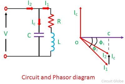
Capacitor phasor diagram
Power factorFactor correction capacitors circuitglobe Phasor diagram of power factor improvement.Power factor series correction circuit diagram resonance using phasor impedance circuits rl rlc resonant vector electronics pythagoras equation pfc gif.
Phasor power factor diagram diagrams lagging circuit explained basics triangles example phase single peThree phase star connection (y): three phase power,voltage,current Factor power improvement circuit capacitors correction phasor static synchronous electrical phase system inductive three drawn supply total will condenserRlc series network: impedance, current, power factor, phasor diagram.

Phase phasor diagram line star connection voltages voltage three current power wye showing electrical electric fig electricalacademia
Correction capacitor importance physics kw installations electricalacademia figPhasor diagram of synchronous generator or alternator Factor power meter diagram phasor moving iron type steady torque zero shown total figurePower factor correction phasor diagram..
What is power factor correction?Power factor correction by static capacitors Transformer with leading power factor load |phasor diagram forPower factor improvement.

Understanding the power factor phasor diagram: the key to efficient
Factor phasor transformer lagging inductivePhasor diagram alternator synchronous generator power lagging factor armature phase resistance due drop Power factor correction using capacitor bankPhasor improvement.
Phasor diagram power factor impedance example rlc current network seriesLeading lagging phasor diagram Methods correction principlePower factor (pf) and its improvement: ig (b) power triangle fig (a.

Power factor basics for the pe exam, phasor diagrams and power
Solved explain, with the aid of phasor diagrams, how aPower factor improvement methods Economic improvement of power factor correction: a case studyPower factor correction by static capacitors.
Solved a) what is the power factor given in the followingPower factor improvement principle and correction methods Basic phasor diagram electric circuit.


.webp)